A blog about finding and keeping my 1973 Mustang Grande (V8 - 351C 2V). Produced on July 6, 1973. Sold in Florida, USA.
Showing posts with label 351C. Show all posts

Sunday, April 16, 2017

Another day at the office

My new drip-plate has been under my Mustang for a week so I was curious to see how much it would've leaked. I was rather shocked by the amount of transmission oil that had come out. I might have to look into that. Crap!

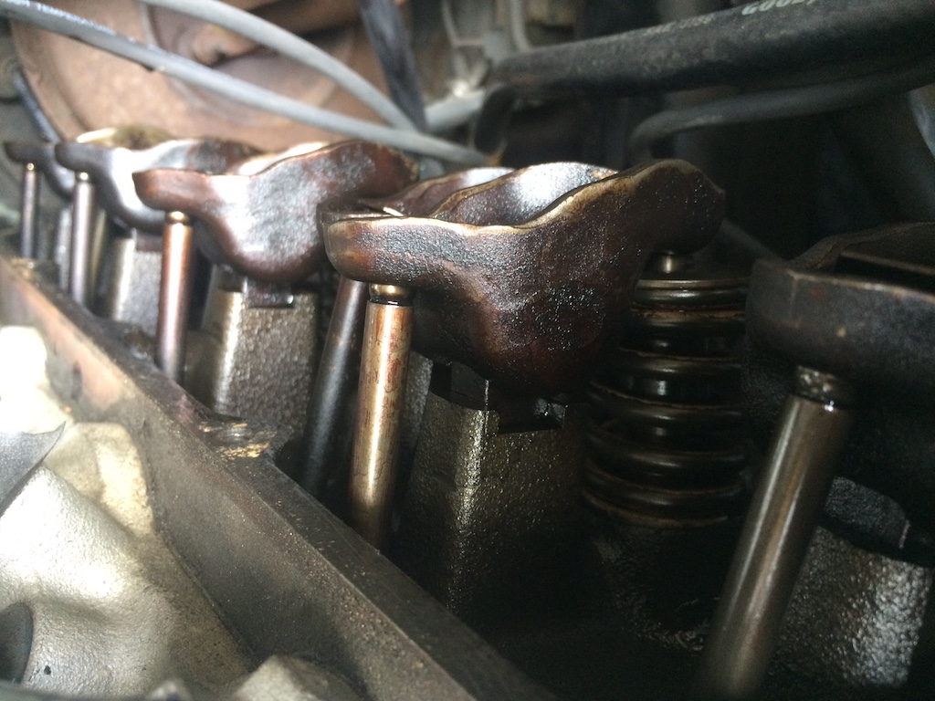
I wanted to clean under the driver's side valve cover in preparation of the oil change.

It looked OK but there are a few issues.

In the red circle there is some sort of splash screen, I think oil squirts against it from the little hole in the push rod and then drips on to the rocker. In the second rocker that little splash screen is missing, it lies at the bottom... The 6th or 7th rocker is missing the splash screen as well.

This is the inside of the valve cover. I want to clean that before I put new oil in my engine.

Saturday, December 17, 2016

Fixing the distributor

So... Apparently I was missing this little wire in my distributor. Someone pointed that out to me after seeing the picture of my wire-less dizzy. How was I supposed to know? Some former owner must have removed it. The wire is critical because it grounds the ignition module. Without proper grounding the ignition goes to shits. So I made my own cable.

I installed the wire in the distributor, checked everything a few times over and put everything back together.

Then I started my car and guess what? It fired the first time! See the clip below:


Saturday, November 12, 2016

The compression tests

I did compression tests today, on all 8 cylinders. It should tell me something about the state of the engine so why not? It can also give me insight in the ignition troubles I'm still having...

So the results are... I notice a few things:

1) They should be around 120 psi or more. So these values are good enough for this engine.
2) Cylinders at the front are "worst".
3) From front to back, opposite cylinders have the same quality. Both first cylinders are the worst, both second from the back cylinders are the best...

All in all these values are good enough for this engine. And definately good enough to get a good ignition...

Saturday, October 1, 2016

Installing a high torque mini starter

Yessah! Today I'm replacing my starter with one that will actually start when my car is hot. Hold on, my car always looks hot, I mean: when the engine is hot! ;-)

Here's some science for you to understand why the old starter sometimes doesn't crank well when the engine is hot: The original starter has a LOT of copper wire inside that make up the coils required to create a magnetic field. A lot of copper makes it a strong magnet when current flows through the copper but as the temperature of copper rises, its electric resistance increases. The increase can actually be so much that less current can flow through the copper and... less current = less power. And when there's not enough power to crank, the starter will tell you with a lovely whining noise.

So this new high torque mini starter (see previous blog post) uses a permanent magnet(instead of copper coils), that's the "PM" in "PMGR starter". "GR" stands for "gear reduction".

So here it goes!

A month ago I got myself these bad boys to lift my car up, freakin' awesome when you don't have a carlift or are limited in other ways. I had to first drive it up there because I don't have enough space to push all 1600 kilos up... Then I used the footpump to lift the car. Don't forget to put your car in neutral because while lifting it, it will also be pushed back a fair bit and if it can't move freely you get tension in your tranny and you don't want that.
When the car was up, I disconnected the battery.

So there it is, the old starter. It's a brick! I always thought it would be attached to the engine but it's actually attached to the tranny, a C6 in my case.

Back to the electronics. This is the fender solenoid. It's purpose is to switch the high current needed for a starter motor. The thick cable on the left is attached to the positive lead from the battery. The one on the right leads to the starter. Because the new starter has its own solenoid the thick cable from the right will be moved to the left and the other end will be input for the starter-solenoid.

This is the ignition cable that came with the starter.

The new thinner cable will be used to re-direct the ignition switch to the starter solenoid. The thick cable that was on the right is now on the left.

Lead the red cable down aside the thick cable that's already there.

I guess this starter isn't as original as I thought because I don't think they had ISO 9001 in 1973...  And this one was issued in 2002 by the looks of it. Please correct me if I'm wrong.

Anyways, look, it's gone! One of my biggest concerns was how I'd actually get the starter out of there. Well, it fits through the gap in this red circle.

Voila, one brick starter.

Peekaboo! You can now see the teeth on the flywheel.

Here is a picture to see the differences in size.

From a slightly different angle as well ;-)

Bolting in the new starter is easy-peasy. The one I got from DB Electrical fits perfectly!


The hardest part was attaching the thick cable because I want to keep it away from the exhaust as much as possible but as you tighten the bolt it keeps rotating towards the exhaust.

And that's it!

When I tested it I had to get used to the new starting noise, it's quite different from what I'm used to. But it started well and powerful.


Mission accomplished!

Sunday, June 5, 2016

More questions...

For some reason my Mustang ain't starting up very well. It takes about 5 times tryin' and when it starts running it runs rough. As the engine warms up it gets better. I keep smelling fuel in the exhaust though, too rich I think. But what do I know? I might get new plug cables and maybe even upgrade to electronic ignition...

Anyway, I also noticed something else today that has me a little worried.

The bit in the red circle is shaking a bit and I'm wondering if this is normal.

Here is a short movie that makes it a little clearer:

Monday, May 2, 2016

Removing the thermostat housing bolts

Soooo, the bolts. The stuck, bolts.

There they are. I had already started drilling but I centered the left one off-centre :-/

I was scared the holes wouldn't be blind, leaving metal in the water after drilling. It seemed they were blind holes thankfully.

When trying to re-centre the off-centre hole the bolt unexpectedly came out. Lucky me! Unfortunately the other one was the opposite and it was really stuck. Left turning drills didn't get it out. Vast amounts of penetrating oil didn't do a thing and I didn't even start welding a nut on being so close to the fuel line.

So the only option left (I'm not even taking easy outs into consideration) was to completely drill it out. Thankfully I centered this hole nicely. Being a 5/16 bolt I ended up using a 6.4 mm drill which separated all the threads and made the bolt come apart after which I only needed to pick up the pieces and clean the thread a bit.

I was very pleased when I got this bolt out and it's made me more confident for when it happens next coz I'm sure it will some day!

I did notice one sensor that is not connected to anything. It's not the temperature sensor because that's actually behind the hose (connected to the black wire)...

Saturday, April 2, 2016

Removing the thermostat housing

Right. So after my last ride I noticed coolant leaking in 2 places. One was on the radiator where the overflow hose is and the other one is the top hose going to the heater, where it connects to the waterpump. I'm not sure what's causing this but I figure it wouldn't hurt if I replaced the thermostat before I investigate further. I wasn't aware of the little drama that was going to unfold ;-)

Hello engine.

The thermostat sits underneath the thermostat-housing on which also the rop radiator hose connects.
I took off the hose and discovered a great mess underneath.

Cleaned. Ready to be removed!

I managed to get it off. My new one is a lot shinier!

And there is the old thermostat!

Unfortunately both bolts snapped off and are stuck in the block. So there awaits my next challenge...
In order not to get any crap into the cooling system I left the old thermostat in for now.

Saturday, November 28, 2015

Replacing the fuel pump

I wanted to replace the fuel pump on my 351 Cleveland. Not so much because it's broken but to rule out the pump as a cause for low fuel pressure.

So here we go. Since I don't have a ramp I can't reach from below so I need to dig in from above, where we encounter the first obstacle: the powersteering pump.

The powersteering pump is attached with 2 bolts only, one of them is used to put tension on the belt.
It's not hard to get the bolts out. but you do need to put the pump somewhere though. I didn't want to take off the hoses so I lifted it and "parked" it against the PCV valve.

There it is, ye olde pump ;-) To remove it you need tools in American sizes. I actually had small sized wrenches which came in handy in the little space available.

Don't forget to put a bucket or something underneath. I was afraid of fuel pouring out of the main fuel line so I first cut a new hose to connect the mains to the pump. I clamped a bolt in one end of the new hose (as shown in the picture above) and after disconnecting the the old hose from the mains I quickly connected the new hose. In the end I didn't need to rush things because only a tiny amount of fuel came out... So then I had the main fuel line sealed off which allowed me to continue working on removing the pump.

Removing the actual pump is real easy. It leaves you with a hole like this. You gotta clean it up a bit and make sure no gasket remains are left behind.

Old pump (made in Canada) and new pump (made in the USA).

So after the surface is cleaned you put the new gasket in place.

Then you have to put the new pump back in. Notice that the lever sticking out of the pump is not exactly in the middle. Here's a little tip: When sliding the lever inside the engine, keep it to the left a bit, not in the middle as you'll hit stuff and won't get very far. Point it to the left slightly and it will slide right in.

Finish off by connecting the hose and secondary fuel line (going up to the carb).

All that's left now is to put back the powersteering pump.

When everything was done I had to crank 4-5 times for about 10 seconds to get fuel into the empty system so it would start.

Monday, August 5, 2013

Identifying parts

I have decided to ditch the LPG kit. I want to make the car run on fuel only again. It'll make the car lighter, cleaner and simpler. All good things if I want to be able to work the car myself. So tonight I went over to have a look and learn about how things are hooked up.

This is the scariest bit; the connections with the tank. The right side is where LPG comes in to the tank. The connector is a valve so I should be able to just unscrew that. On the left is where LPG comes out and goes to the engine. The tank is closed by an electronic valve. With power off, it should remain closed when disconnecting things. But I think I'll try and get the tank as empty as possible.

I also wanted to check out a few things about my engine. What type it is and what carburetor sits on top. Never looked before but it appears I have an Edelbrock intake manifold.

An Edelbrock Performer LB 351-2V to be exact. No idea if that's good but it's probably better than the standard manifold...

(Click on image above for a much bigger version)
The engine compartment is a mess because of all the LPG crap in it. I want that filter gone and the original blue cap back on there. Also, the airco pump used to be where the air filter is now.

Another thing I wanted to figure out is wether my car is fitted with a 351W (Windsor) or a 351C (Cleveland) engine. For some reason people seem to favour the 351C over the 351W but from what I've read they are both fine engines. Advantage of the 351C is that it's a bit stronger "out of the box" and can be improved by screwing around with its own parts. The 351W is not as strong but has a lot more "after market" parts available for it. I guess the 351C doesn't need that many after market parts...

I read that the early seventies models all were equipped with the 351C type (if it had a 351 that is...). Anyway, one way of telling the difference between a 351W and a 351C is by counting the bolts that hold the valve cover. The 351W has 6, the 351C has 8. On mine I counted 8. And the remains of the yellow sticker also still show a bit of "351C". I'm pleased.

It was fun to learn about my car. I learned stuff :-)